
Spring-Mass-Damper Kit - Tutorial
Topics:
-
General Features and Quick Start
Examples with DAQ1 (USB), follow the sequence of examples:
-
Example Experiment: Spring Rate Coefficient Measurement with DAQ1 (USB)
-
Example Experiment: System Response to Step Force Input (1DOF and 2DOF Plants) with DAQ1 (USB)
-
Example Experiment: Sweep Frequency Response with DAQ1 (USB)
Examples with DAQ2 (NI PCIe-6321), follow the sequence of examples:
Safety Guidelines
(updated on 7/9/2026)


Safety Guidelines
If improperly used, EMB can cause serious injuries!
Every user must read and understand the EMB Safety Manual before using this kit: EMB SAFETY MANUAL (MUST READ)

General Features and Quick Start
The EMB Spring-Mass-Damper Kit (SMD Kit) consists of 1 or more linear slides with optical linear encoder, an actuator with rack and pinion, one or more springs, one or more dashpots, mass blocks, hard stops, the optical breadboard and complementary components.

IMPORTANT: Operate the device only in the approved orientation, with the breadboard plate parallel to the table surface.
Operation in a perpendicular or angled orientation is prohibited and may result in equipment damage, instability, or personal injury.
Failure to follow these instructions may result in serious injury or equipment damage!
Robots5 assumes no responsibility or liability for injury, damage, or loss resulting from improper installation, improper use, or failure to follow the safety instructions and operating guidelines provided in this manual.
Correct Orientation: The breadboard plate must be positioned parallel to the table surface during operation:

Prohibited Configuration: Never operate the unit with the breadboard plate perpendicular to or angled relative to the table surface:

Certain components are secured with Torx fasteners, which are factory-installed and not intended for user access. These fasteners must not be removed, loosened, or adjusted by the user.
Removal or modification of Torx fasteners may compromise mechanical alignment, create unsafe operating conditions, and result in equipment damage.
Users should only interact with Hex fasteners (not Torx!).

Before using the EMB system, ensure the following:
-
All users read the safety section above and are following safety precaution
-
The power supply to the amplifier is turned off
-
The E-STOP button is pressed to disable any potential motion
-
All components such as mass blocks, springs, and dashpots are properly installed and secured for motion
-
The hard stops are properly installed and tested by manually moving the linear slide
Follow the next procedures to run your experiment:
-
Step 1: Plug the EMB-DAQ to the computer
-
Step 2: With the E-STOP button still engaged (disabled), turn on the amplifier power supply. We recommend setting the power supply to 12 V with a 3 A current limit. The ESCON amplifier should power on but remain disabled, as indicated by the red LED. The amplifier's default configuration is Current Mode, so increasing the power supply voltage to 18 V or 24 V will not significantly affect the system's response. However, using a higher supply voltage provides additional headroom to absorb regenerative energy returned from the motor to the power supply.
-
Step 3: Start your software application (MATLAB® and Simulink® for example)
-
Step 4: Enable the E-STOP (turn to reset). The ESCON amplifier should still have a red LED, as the input signal (PWM) and the enable signal are not proper yet (ESCON2 with analog voltage input behavior is slightly different)
-
Step 5: Run your code in the DAQ and be ready for motion
Immediately press the E-STOP in case of unexpected behavior or emergency!
To turn off the system, follow these steps:
-
Press the E-STOP button
-
Turn-off the ESCON power supply
-
Close the software application (MATLAB® and Simulink® for example)
-
For USB-based DAQ: Either unplug the DAQ PWR USB cable from the computer or turn the computer off completely. The DAQ LED should not be illuminated when not in use.
-
For PCIe-based DAQ: we recommend to turn the computer off. The DAQ PWR LED should not be illuminated when not in use.
We strongly advise against leaving the EMB-DAQ and associated electronics powered on for extended periods, such as overnight.
While physically unplugging the USB from the computer or DAQ will power it off, it can cause wear to the USB connector over time. Therefore, turning off the USB port via software or shutting down the computer is the preferred method.
Power Supply for Maxon ESCON
To power the Maxon ESCON with a laboratory power supply, use the included cables to connect to the + and - binding posts using the banana plugs or cables with ferrules with the thumb nuts, as pictured below:


Drive System (Rack and Pinion)
An actuator (EMB-AM2 or EMB-AM4 for example) drives a rack and pinion, applying a force to a carriage. The standard pinion we configure our kits is metric, stainless steel, has 20 teeth, and is module 20. The theoretical acting force radius is 0.01 m (pitch circle).

A small amount of backlash between the rack and pinion gear is normal. During assembly, we use precision gauges and fixtures to set the backlash to the optimal specification.
With the rack and pinion engaged, the carriage should move smoothly throughout its full range of travel when slid by hand. There should be no significant binding, sticking, or locking. If the motion is not smooth, the rack height should be adjusted.
In some cases, the rack may need to be adjusted or reinstalled, particularly if you notice excessive backlash, increased play, or sticky carriage movement. This procedure can be performed by the user; there is no need to return any hardware to the factory. We can provide remote guidance and step-by-step instructions throughout the process. The procedure requires a set of alignment pins and feeler gauges.
Beginning in mid-2026, we introduced an updated rack design that uses a white polyacetal rack instead of the earlier blue nylon version. Polyacetal offers improved dimensional stability and provides smoother, more consistent carriage motion over time. If your system is equipped with the blue nylon rack and you are interested in upgrading to the new design, contact us.
If you wish to remove the actuator, for example to perform free vibration studies without the influence of the pinion and actuator dynamics, we recommend keeping the actuator clamp attached to the breadboard and loosening the dovetail instead, sliding the actuator backwards, disengaging the pinion from the rack. To slide the actuator back, loosen the dovetail screws (2 screws with green arrows in the image below). Doing it this way, the alignment of the motor assembly to the rack, and rack orientation and height are still maintained for later installation.


To achieve the correct axial position of the motor—and, consequently, the proper alignment between the pinion gear and the rack—adjust the motor module rather than loosening or removing the pinion gear. Position the motor so that the face of the pinion gear is approximately flush with the face of the rack, as indicated by the red arrows in the illustration below.
This alignment does not need to be exact and can be set approximately by eye and feel. After adjusting the motor position, verify that the motor shaft does not contact the carriage or any other component throughout the full range of motion. The carriage should move smoothly over its entire travel, with no binding, rubbing, or other signs of interference.

Springs
Our spring kit comes with 4 stainless steel springs with the following nominal parameters:
-
Spring 1: rate 90 N/m, length: 85 mm
-
Spring 2: rate 225 N/m, length: 90 mm
-
Spring 3: rate 520 N/m, length: 90 mm
-
Spring 4: rate 812 N/m, length: 90 mm

A round stainless steel plate with an M5 thread is welded to each side of the springs. Our springs are symmetric (left and right are the same).
For typical Spring-Mass-Damper plants, one end of the spring is mounted to the moving carriage side plate and the other to a spring bracket. The same M5 fasteners are used with oversized washers (larger outside diameter only).
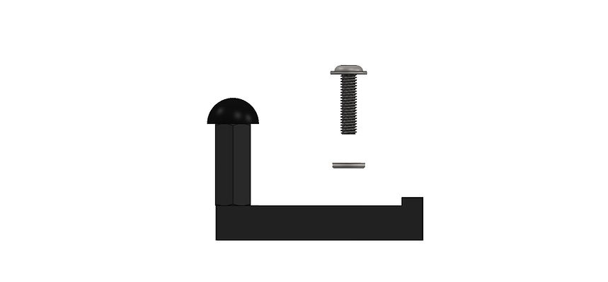
To secure the spring bracket to the breadboard, an M6 fastener and washer is used (orient the washer face with the rounded edge away from the anodized surface, so no surface damage occurs due to washer edge burrs):

A 4 mm hex tool is used to fasten both types of fasteners (included).
To ensure proper spring installation, avoid twisting the spring. Instead of fully tightening one side before the other, screw each side in incrementally. Once both sides are initially secured, slightly loosen the first side to relieve any rotational tension. Then, tighten it completely in its resting position.
With every spring, we include the nominal spring rate coefficient. For a more accurate value, a spring measurement experiment can be performed with the Spring-Mass-Damper Kit. We provide the code and instructions.
Below is a plot and experimental coefficients (older spring model with nominal rate of 450 N/m):

As a reminder, when handling springs, be aware of the potential energy stored and the risk of sudden release.
Never exceed the recommended load or extension limits of our springs, this will damage the spring permanently!
Mass Blocks
To change the mass properties of the linear systems, the user can add or remove mass blocks. These blocks are machined brass measuring 2" by 2" by 1/2" with a 1/4" clearance hole in the center.
The finish is electroless nickel plate to provide the best wear and tear resistance.

The fastener is determined by the number blocks stacked (different lengths), the dovetail clamp and square nut are the same:


A 4 mm hex tool is used to fasten these M6 flanged button head fasteners.
Using the wrong fastener can damage the carriage and create a safety hazard. If the fastener is too long, it will bottom out against the carriage surface. If it is too short, it will not properly engage the M6 square nut.
To get an accurate mass parameter, we advise measuring with a scale each "mass assembly".
The nominal values are:
-
Dovetail clamp only = 62 g
-
Dovetail clamp, 1 Block, square nut, M6X22 fastener = 348 g
-
Dovetail clamp, 2 Block, square nut, M6X35 fastener = 628 g
-
Dovetail clamp, 3 Block, square nut, M6X45 fastener = 908 g
Don't forget to add the mass of the carriage, nominal 520 g.
Always make sure the mass blocks and dovetail clamp are firmly secured before running any experiment with EMB!
Dashpot
The dashpot is a delicate module, due to use of graphite piston, glass body, and aluminum rod with necked reliefs near the ball-joints (safety feature).
Our EMB dashpot has a limited stroke of 76 mm (approximately 3 inches). It is crucial that the dashpot module is not used as a hard stop for any EMB plant. End-of-travel collisions can cause permanent damage to the module. To prevent this, external hard stops must be implemented to limit travel.
For typical Spring-Mass-Damper plants, the moving rod side of the dashpot with a 10-32 stud is mounted to the carriage side plate by the 3/8" hex nut. We include a wrench with the dashpot assembly. During installation, hold the 10-32 stud with your finders while torqueing the 3/8" hex nut with the wrench. The use of a locking washer is option (we include one with the kit).
Be careful not to bend or damage the moving rod (it has a necked portion near the ball joint) and the glass.
To secure the dashpot bracket to the breadboard, an M6 fastener and washer is used (orient the washer face with the rounded edge away from the anodized surface, so no surface damage occurs due to washer edge burrs):

When adding the dashpot module to your plant, make sure the moving rod and the body of the dashpot are as collinear as you can. Excessive misalignment will result in rapid wear and tear of this component.
To adjust damping, turn the knob clockwise to increase and counterclockwise to decrease damping. The nominal damping range is from 0-40 lbf-s/in, 0-7 N-s/mm.
The damping adjustment knob can be removed to provide the smallest amount of damping while the dashpot module is installed.
Do not completely close the dashpot as it will damage the device or can potentially break in a dangerous fashion!
Hard Stops
The proper use of hard stops is critical to prevent permanent damage of the linear slides and/or dashpot module from an end of travel collision, by limiting the travel to a safe region.
The contact point on our hard stops have a durometer 70A rubber bumper. There should never be metal-to-metal contact!
To secure the hard stop to the breadboard, an M6 fastener and washer is used (orient the washer face with the rounded edge away from the anodized surface, so no surface damage occurs due to washer edge burrs):

If the fastener is excessively tight and requires additional torque for removal, use the L-Allen wrench supplied with the EMB-Spring Set rather than the precision screwdrivers to avoid tool damage and ensure proper leverage.
The placement of the hard stops vary depending on your plant configuration and needs, we recommend at least 10 millimeters of buffer, between the internal hard stop of the linear slides (EMB-LM1 or EMB-LM2) and the external hard stop. Remember, the internal hard stops of the linear slides should never be used as system hard stops, as they are not meant for external loading, only internal to hold the bearing balls in place. Please refer to the EMB-LM1 manual for additional details.
For the Spring-Mass-Damper Kits with multiple carriages (2DOF and 3DOF), the space between carriages is limited and typically only 1 hard stop is required. A 2DOF Spring-Mass-Damper Kit uses 3 hard stops (left, middle, right), and a 3DOF uses 4 hard stops (left, middle, middle, right). Note: we include 2 hard stops for the 1DOF, 4 hard stops for the 2DOF, and 6 hard stops for the 3DOF (due to shipping and to provide additional design flexibility for different plant configurations).
The following image is a 2DOF Spring-Mass-Damper Kit with 3 hard stops installed (left, middle, and right):

End of Travel Limit Switches (EoTS)
As an optional module for our EMB systems, the End-of-Travel Switches (EoTS) enhance functionality and safety. Their primary purpose is to serve as limit switches: when triggered, a fault is generated and the system stops. Additionally, the EoTS can be used to home the carriage position.
The only contact point of the switch and the moving carriage should be the switch lever.
We offer a right and a left EoTS designed for each side of the linear slide.
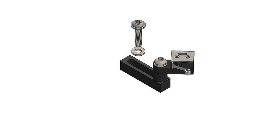
To secure the hard stop to the breadboard, an M6 fastener and washer is used (orient the washer face with the rounded edge away from the anodized surface, so no surface damage occurs due to washer edge burrs):

These EoTS should not be used as hard stops, this will cause permanent damage. The switches should be placed right before a hard stop. Make sure the switch opens (clicks) but the switch doesn't bottom out before hitting the hard stop.
For placement, you can make use of the mount slot and the angle adjustment M6 fastener. Make sure all fasteners are secured before running experiments and no cables are on the travel path (cables not shown in renders).
Connect the EoTS switches to the EMB-EoTS Module with the 3.5mm stereo connectors. The EoTS module connects to the EMB-DAQ1/EMB-DAQ2 using the cable with pigtail with ferrules (no polarity).
Depending on the size of your kit and the number of switches, the EMB-EoTS module will have 2, 4, or 6 switch inputs. These inputs are connected in series and all switches must be connected for the circuit to be closed.
Nomenclature legend:
- SW1-L: Left Switch of carriage 1
- SW1-R: Right Switch of carriage 1
- SW2-L: Left Switch of carriage 2
- SW2-R: Right Switch of carriage 2
- SW3-L: Left Switch of carriage 3
- SW3-R: Right Switch of carriage 3

Similar to hard stops, for the Spring-Mass-Damper Kits with multiple carriages (2DOF and 3DOF), the space between carriages is limited and typically only 1 switch is used (facing the motor carriage) or no end-of-travel switches are used in the middle. A 2DOF Spring-Mass-Damper Kit can use 2 or 3 switches, and a 3DOF can use 2 or 3 switches.
Note: these module is optional, but when purchased with a kit, we include 2 hard stops for the 1DOF, 4 hard stops for the 2DOF, and 6 hard stops for the 3DOF. We include more switches than normally used in the standard configuration to provide additional design flexibility for different plant configurations.
The following image is a 2DOF Spring-Mass-Damper Kit with 3 hard stops installed (left, middle, and right) and 2 EoTS:


When driving the motor, for instance in a Controls experiment, we strongly recommend using end-of-travel switches on both sides of the driving carriage (with the rack-and-pinion).
The following image is a 2DOF Spring-Mass-Damper Kit with 3 hard stops installed (left, middle, and right) and 3 EoTS (2 on the driving carriage and 1 on the second carriage):


Example Experiment: Force Input Response with DAQ1 (USB)
(updated on 7/9/2026)
EXAMPLE: Force Input Response
As a starting example, we will develop a model to apply a force to spring-mass-damper carriage. This is going to drive (pun intended!) many of the other examples and experiments!
We will be using an an EMB-SMD 1DOF kit, with EMB-AM4 actuator, a maxon ESCON amplifier in current mode (standard configuration), and an EMB-DAQ1 with MATLAB® and Simulink®.
You can download the model by clicking here: R5_EMB_SMDS_FORCE_INPUT.ZIP (62KB) or from our GitHub. Make sure to always use the latest version.
Note that applying a force to the carriage will cause the carriage to move! Make sure you account for this motion, either with a spring or force sensor (what we used in this example, see pictures below).
Start with low forces (1N, 2N...). 10N+ is a very significant force!
Always be aware of the carriage(s) location before running the program, as the encoder is an incremental encoder, not absolute. When the program starts, the encoder position is set to zero.
Make sure the carriage travel is sufficient for the experiment. Limit the input force as necessary to avoid end of travel collisions. The hard-stops must be properly installed before running any model!

To apply a force to the carriage, we apply a current to the motor. With the ESCON configured in current mode (refer to maxon ESCON Amplifier - Tutorial for details), we input a PWM to the N0 block (General Pulse Output), with a gain of 0.159. Note that we need to bias the PWM signal (0.1 to 0.9 range for the ESCON) and take the absolute value of the input signal.
To convert force to current, we divide the pinion radius by the torque constant of the motor. The pinion used has 20 teeth and has module 1.0, therefore the theoretical radius is 0.01m. You can update the motor efficiency (motor_eff in the script) to better match the hardware.
For the direction of the force, we use a "Compare To Zero" block and set the Digital Output as high/low.

To run the model:
-
In the MATLAB® Command Window, enter the sampling time (T=0.002, for example) and simulation Stop Time (S=5, for example). These variables can be incorporated into a MATLAB® Script (.m file) that runs before the Simulink® model. We included an .m script with the link above for download. The maximum real-time sampling rate of this board is up to 1024 Hz. We recommend using sampling time between 0.001s to 0.010, depending on your model. Be careful with signal noise due to spatial quantization and excessive phase lag. We find a sampling time of about 0.002 to 0.004s is a good balance for our electro-mechanical plants.
-
In Simulink®, open R5_EMB_SMDS_FORCE_INPUT model, enter the DESKTOP REAL-TIME tab, and click Run in Real-Time. If you run the model from the SIMULATION tab (green Run button), it won't work properly, and the EMB-DAQ1 will need to be reset. To reset the DAQ, power cycling the board is required by unplugging the USB cable and DAQ power cable, waiting 10 seconds, and plugging back into the computer and power supply.
-
After clicking in Run in Real-Time, many processes take place, including building, code generation, and deployment of code to the target. These processes take between 5s and 30s.
-
If the model doesn't run, check if the E-STOP or one of the End-of-Travel-Switches (optional) are pressed.
-
To stop the model from running, you can click Stop in Simulink®, press the E-STOP (if configured), press the End-of-Travel-Switch, or any logic fed into the Stop Simulation Block in Simulink®. We strongly recommend the use of these features to keep operation of EMB safe!

Below is a sample plot of input and measure current values, from a manual step of force with magnitude of 5N, carriage touching a force sensor:


Example Experiment: Spring Rate Coefficient Measurement with DAQ1 (USB)
(updated on 7/9/2026)
EXAMPLE: Spring Rate Coefficient Measurement
With this example, we measure the rate coefficient (k) of a spring. The setup uses our EMB-SMD 1DOF kit, with EMB-AM4 actuator, a maxon ESCON amplifier in current mode (standard configuration), and an EMB-DAQ1 with MATLAB® and Simulink®. One end of a spring is attached to the carriage side plate and the other is grounded by the spring bracket.
In this example,we used Spring #4, if you want to use a different spring, change the input force (damage to the spring might occur otherwise).

You can download the model by clicking here: R5_EMB_SMDS_SPRING_RATE.ZIP (343KB) or from our GitHub. Make sure to always use the latest version.
Always be aware of the carriage(s) location before running the program, as the encoder is an incremental encoder, not absolute. When the program starts, the encoder position is set to zero.
Make sure the carriage travel is sufficient for the experiment. Limit the input force as necessary to avoid end of travel collisions.
Note that we used the previous example's model, Force Input Response, and created a Subsystem to better organize and simplify the model.

As before with the previous example, to apply a force to the carriage, we apply a current to the motor. With the ESCON configured in current mode (refer to maxon ESCON Amplifier - Tutorial for details), we input a PWM to the N0 block (General Pulse Output), with a gain of 0.159. Note that we need to bias the PWM signal (0.1 to 0.9 range for the ESCON) and take the absolute value of the input signal.
To convert force to current, we divide the pinion radius by the torque constant of the motor. The pinion used has 20 teeth and has module 1.0, therefore the theoretical radius is 0.01m.
For the direction of the force, we use a "Compare To Zero" block and set the Digital Ouput as high/low.
The Subsystem is pictured below:

To run the model:
-
In the MATLAB® Command Window, enter the sampling time (T=0.001, for example) and simulation Stop Time (S=5, for example). These variables can be incorporated into a MATLAB® Script (.m file) that runs before the Simulink® model. We included an .m script with the link above for download. We recommend using sampling time between 0.001s to 0.010, depending on your model. Be careful with signal noise due to spatial quantization and excessive phase lag. We find a sampling time of about 0.004s is a good balance for our electro-mechanical plants.
-
In Simulink®, open R5_EMB_SMDS_SPRING_RATE model, enter the DESKTOP REAL-TIME tab, and click Run in Real-Time. If you run the model from the SIMULATION tab (green Run button), it won't work properly, and the EMB-DAQ1 will need to be reset. To reset the DAQ, power cycling the board is required by unplugging the USB cable and DAQ power cable, waiting 10 seconds, and plugging back into the computer and power supply.
-
After clicking in Run in Real-Time, many processes take place, including building, code generation, and deployment of code to the target. These processes take between 5s and 30s.
-
If the model doesn't run, check if the E-STOP or one of the End-of-Travel-Switches (optional) are pressed.
-
To stop the model from running, you can click Stop in Simulink®, press the E-STOP (if configured), press the End-of-Travel-Switch, or any logic fed into the Stop Simulation Block in Simulink®. We strongly recommend the use of these features to keep operation of EMB safe!

After the experiment runs, we can plot Force vs. Displacement and fit a line to get the spring rate (k=869.8 N/m in this example):

Reminder:
Never exceed the recommended load or extension limits of our springs, this will damage the spring permanently!
Example Experiment: System Response to Step Force Input with DAQ1 (USB)
(updated on 7/9/2026)
EXAMPLE: System Response to Step Force Input
With this example, we study the response of a Spring-Mass-Damper System to a force input. The setup uses our EMB-SMD 1 or 2 DOF kit, with an EMB-AM4 actuator, a maxon ESCON amplifier in current mode (standard configuration), and an EMB-DAQ1 (or 2 for the 2DOF system) with MATLAB® and Simulink®. You can reconfigure the plant to stuff different dynamics, such as changing springs, mass, and dashpot.
You can download the model here:
R5_EMB_SMDS_STEP_RESPONSE_1DOF.ZIP (345KB)
R5_EMB_SMDS_STEP_RESPONSE_2DOF.ZIP (322KB)
or from our GitHub. Make sure to always use the latest version.
Always be aware of the carriage(s) location before running the program, as the encoder is an incremental encoder, not absolute. When the program starts, the encoder position is set to zero.
Make sure the carriage travel is sufficient for the experiment. Limit the input force as necessary to avoid end of travel collisions.
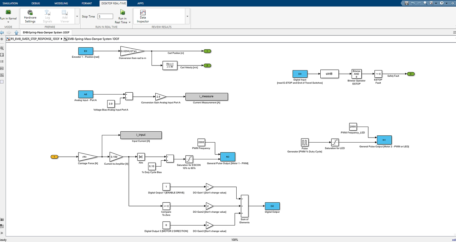
Simulink® models for 1DOF and 2DOF systems:


As before with the previous example, to apply a force to the carriage, we apply a current to the motor. With the ESCON configured in current mode (refer to maxon ESCON Amplifier - Tutorial for details), we input a PWM to the N0 block (General Pulse Output), with a gain of 0.159. Note that we need to bias the PWM signal (0.1 to 0.9 range for the ESCON) and take the absolute value of the input signal.
To convert force to current, we divide the pinion radius by the torque constant of the motor. The pinion used has 20 teeth and has module 1.0, therefore the theoretical radius is 0.01m. We use an experimental value that provides a better approximation, for example 0.0105m (actual radius, or r_act).
For the direction of the force, we use a "Compare To Zero" block and set the Digital Ouput as high/low.
The Subsystem for 1DOF and 2DOF are pictured below:

To run the model:
-
In the MATLAB® Command Window, enter the sampling time (T=0.002, for example) and simulation Stop Time (S=5, for example). These variables can be incorporated into a MATLAB® Script (.m file) that runs before the Simulink® model. We included an .m script with the link above for download. The maximum real-time sampling rate of this board is up to 1024 Hz. We recommend using sampling time between 0.001s to 0.010, depending on your model. Be careful with signal noise due to spatial quantization and excessive phase lag. We find a sampling time of about 0.002 to 0.004s is a good balance for our electro-mechanical plants.


-
In Simulink®, open R5_EMB_SMDS_STEP_RESPONSE_1/2DOF model open, enter the DESKTOP REAL-TIME tab, and click Run in Real-Time. If you run the model from the SIMULATION tab (green Run button), it won't work properly, and the EMB-DAQ1 will need to be reset. To reset the DAQ, power cycling the board is required by unplugging the USB cable and DAQ power cable, waiting 10 seconds, and plugging back into the computer and power supply.
-
After clicking in Run in Real-Time, many processes take place, including building, code generation, and deployment of code to the target. These processes take between 5s and 30s.
-
If the model doesn't run, check if the E-STOP or one of the End-of-Travel-Switches (optional) are pressed.
-
To stop the model from running, you can click Stop in Simulink®, press the E-STOP (if configured), press the End-of-Travel-Switch, or any logic fed into the Stop Simulation Block in Simulink®. We strongly recommend the use of these features to keep operation of EMB safe!
Example Experiment: Sweep Frequency Response with DAQ1 (USB)
(updated on 7/10/2026)
EXAMPLE: Sweep Frequency Response
We take the force example further and input a sweep signal (chirp signal).
The setup uses our EMB-SMD 1DOF kit, with EMB-AM4 actuator, a maxon ESCON amplifier in current mode (standard configuration), and an EMB-DAQ1 with MATLAB® and Simulink®. One end of a spring is attached to the carriage side plate and the other is grounded by the spring bracket.
In this example,we used Spring #4, if you want to use a different spring, change the input force and frequency (damage to the spring might occur otherwise).
You can download the model by clicking here: EMB_SMDS_SWEEP_INPUT_DAQ1.ZIP (340KB) or from our GitHub. Make sure to always use the latest version.
Note: Start with small Sweep Amplitude Gain!
Always be aware of the carriage(s) location before running the program, as the encoder is an incremental encoder, not absolute. When the program starts, the encoder position is set to zero.
Make sure the carriage travel is sufficient for the experiment. Limit the input force as necessary to avoid end of travel collisions.
Note: Be extremely careful if you are applying a force to the cart if you don't have a spring and this will likely drive the cart to the end of travel, damaging the carriage if not properly limited.

As before with the previous example, to apply a force to the carriage, we apply a current to the motor. With the ESCON configured in current mode (refer to maxon ESCON Amplifier - Tutorial for details), we input a PWM to the N0 block (General Pulse Output), with a gain of 0.159. Note that we need to bias the PWM signal (0.1 to 0.9 range for the ESCON) and take the absolute value of the input signal.
To convert force to current, we divide the pinion radius by the torque constant of the motor. The pinion used has 20 teeth and has module 1.0, therefore the theoretical radius is 0.01m.
For the direction of the force, we use a "Compare To Zero" block and set the Digital Ouput as high/low.
The Subsystem is pictured below:

To run the model:
-
In the MATLAB® Command Window, enter the sampling time (T=0.002, for example) and simulation Stop Time (S=5, for example). These variables can be incorporated into a MATLAB® Script (.m file) that runs before the Simulink® model. We included an .m script with the link above for download. The maximum real-time sampling rate of this board is up to 1024 Hz. We recommend using sampling time between 0.001s to 0.010, depending on your model. Be careful with signal noise due to spatial quantization and excessive phase lag. We find a sampling time of about 0.002 to 0.004s is a good balance for our electro-mechanical plants.
-
In Simulink®, open R5_EMB_SMDS_SWEEP_INPUT_DAQ1 model, enter the DESKTOP REAL-TIME tab, and click Run in Real-Time. If you run the model from the SIMULATION tab (green Run button), it won't work properly, and the EMB-DAQ1 will need to be reset. To reset the DAQ, power cycling the board is required by unplugging the USB cable and DAQ power cable, waiting 10 seconds, and plugging back into the computer and power supply.
-
After clicking in Run in Real-Time, many processes take place, including building, code generation, and deployment of code to the target. These processes take between 5s and 30s.
-
If the model doesn't run, check if the E-STOP or one of the End-of-Travel-Switches (optional) are pressed.
-
To stop the model from running, you can click Stop in Simulink®, press the E-STOP (if configured), press the End-of-Travel-Switch, or any logic fed into the Stop Simulation Block in Simulink®. We strongly recommend the use of these features to keep operation of EMB safe!

Reminder:
Never exceed the recommended load or extension limits of our springs, this will damage the spring permanently!
Sweep experiments tend have a long duration time (over 20 seconds for example) and this might require the user to adjust the Simulink External Signal & Triggering Duration to acquire more data. To do so, inside the Desktop Real-Time tab in Simulink, under the prepare region, select the "Control Panel":

Next, click in "Signal & Triggering", select the signal(s) and change the Duration to fit your experiment. This value is calculated as (1/T * S + 1). T is the sampling time and S is the duration. Example: for a 30 second long sweep experiment with sampling time of 0.001, the formula would produce: (1/0.001 * 30 + 1) = 30001. As long as your value is larger than the calculated value, you will be able to acquire data for your complete experiment. If a lower number is set, you will miss data.


Note for Sweep Parameter Selections:
When selecting the frequency range for a sine sweep on a spring–mass–damper system, choose a minimum frequency that is low enough to capture the system's low-frequency behavior but not so low that the experiment becomes unnecessarily long or is dominated by static friction, drift, or sensor offsets.
Avoid starting at exactly 0 Hz, since a sinusoidal excitation is not defined at zero frequency and provides no meaningful dynamic information. The maximum frequency should extend well beyond the expected natural frequency so that the resonance peak, phase transition, and high-frequency roll-off are all observed. At the same time, avoid sweeping far beyond the useful bandwidth of the actuator and sensors, where the response is increasingly affected by noise and hardware limitations rather than the plant dynamics.
The sweep time should be selected as a compromise between measurement accuracy and experiment duration. If the sweep progresses too quickly, the excitation frequency changes faster than the system can reach its steady-state response, resulting in distorted estimates of the frequency response. Conversely, an excessively slow sweep increases the total experiment time without significantly improving the results and may introduce errors due to thermal drift, changing friction, or other time-varying effects. A moderate sweep rate that allows the system to respond at each frequency generally provides the best balance.
Finally, avoid using exact boundary values such as 0 Hz, 10 Hz, or round-number durations when practical. Slightly offset values (for example, 0.1 Hz instead of 0 Hz, or 9.9 Hz instead of 10 Hz) help avoid numerical edge cases and potential synchronization with the sampling process. While the exact values are not critical, selecting practical frequency limits and a reasonable sweep duration leads to more reliable and repeatable frequency-response measurements.
Example Experiment: Force Input Response with DAQ2 (NI PCIe-6321)
(updated on 3/6/2026)
EXAMPLE: Force Input Response
As a starting example, we will develop a model to apply a force to spring-mass-damper carriage. This is going to drive (pun intended!) many of the other examples and experiments!
We will be using an an EMB-SMD 2DOF kit, with EMB-AM2 actuator (brushless motor), a maxon ESCON2 amplifier in current mode (standard configuration, with sinusoidal commutation, analog input for the current setpoint), and an EMB-DAQ2 (NI PCIe-6321) with MATLAB® and Simulink®.
You can download the model by clicking here: EMB_SMDS_FORCE_INPUT_DAQ2.ZIP (326KB) or from our GitHub. Make sure to always use the latest version.
This is a complete model, with the ESTOP digital input and EoTS (end-of-travel switch) safety features implemented, analog inputs for average current and average motor velocity, 2 encoder inputs for each cart, the user LED blinking when the code runs, the enable pin for the ESCON enable (digital output from EMB-DAQ2), and force to the carriage as input (converts to torque, then current, then analog voltage output to the ESCON2 in the range of -10V to 10V).
Note: For a student lab setting, we recommend adding virtual end-of-travel conditions for each carriage (we can assist with this implementation).
Always be aware of the carriage(s) location before running the program, as the encoder is an incremental encoder, not absolute. When the program starts, the encoder position is set to zero.
Make sure the carriage travel is sufficient for the experiment. Limit the input force as necessary to avoid end of travel collisions.
Be extremely careful if you are applying a force to the cart if you don't have a spring and this will likely drive the cart to the end of travel, damaging the carriage if not properly limited.

To apply a force to the carriage, we apply a current to the motor. With the ESCON2 configured in current mode (refer to maxon ESCON2 Amplifier - Tutorial for details). The current setpoint is set by the analog output block (scale of -10V for -5A and +10V for +5A).
To convert force to current, we divide the pinion radius by the torque constant of the motor. The pinion used has 20 teeth and has module 1.0, therefore the theoretical radius is 0.01m.

To run the model:
-
In the MATLAB® Command Window, enter the sampling time (T=0.001, for example) and simulation Stop Time (S=5, for example). These variables can be incorporated into a MATLAB® Script (.m file) that runs before the Simulink® model. We included an .m script with the link above for download. We recommend using sampling time between 0.001s to 0.010, depending on your model. Be careful with signal noise due to spatial quantization and excessive phase lag. We find a sampling time of about 0.004s is a good balance for our electro-mechanical plants.
-
In Simulink®, open the model open, enter the DESKTOP REAL-TIME tab, and click Run in Real-Time. If you run the model from the SIMULATION tab (green Run button), it won't work properly.
-
After clicking in Run in Real-Time, many processes take place, including building, code generation, and deployment of code to the target. These processes take between 5s and 20s.
-
If the model doesn't run, check if the E-STOP or one of the End-of-Travel-Switches (optional) are pressed.
-
To stop the model from running, you can click Stop in Simulink®, press the E-STOP (if configured), press the End-of-Travel-Switch, or any logic fed into the Stop Simulation Block in Simulink®. We strongly recommend the use of these features to keep operation of EMB safe!

You can change the input from constant to a different source, such as sine input or sweep, as shown in the next example.
Example Experiment: Sweep Frequency Response with DAQ2 (NI PCIe-6321)
(updated on 3/6/2026)
EXAMPLE: Sweep Frequency Response
We take the force example further and input a sweep signal (chirp signal).
We will be using an an EMB-SMD 2DOF kit, with EMB-AM2 actuator (brushless motor), a maxon ESCON2 amplifier in current mode (standard configuration, with sinusoidal commutation, analog input for the current setpoint), and an EMB-DAQ2 (NI PCIe-6321) with MATLAB® and Simulink®.
It has a medium spring (Spring #3) to ground and cart1, and a hard spring (Spring #4) between cart1 and cart2.
You can download the model by clicking here: EMB_SMDS_SWEEP_INPUT_DAQ2.ZIP (321KB) or from our GitHub. Make sure to always use the latest version.
This is a complete model, with the ESTOP digital input and EoTS (end-of-travel switch) safety features implemented, analog inputs for average current and average motor velocity, 2 encoder inputs for each cart, the user LED blinking when the code runs, the enable pin for the ESCON enable (digital output from EMB-DAQ2), and force to the carriage as input (converts to torque, then current, then analog voltage output to the ESCON2 in the range of -10V to 10V).
Note: For a student lab setting, we recommend adding virtual end-of-travel conditions for each carriage (we can assist with this implementation).
Note: Start with small Sweep Amplitude Gain!
Always be aware of the carriage(s) location before running the program, as the encoder is an incremental encoder, not absolute. When the program starts, the encoder position is set to zero.
Make sure the carriage travel is sufficient for the experiment. Limit the input force as necessary to avoid end of travel collisions.
Note: Be extremely careful if you are applying a force to the cart if you don't have a spring and this will likely drive the cart to the end of travel, damaging the carriage if not properly limited.

To apply a force to the carriage, we apply a current to the motor. With the ESCON2 configured in current mode (refer to maxon ESCON2 Amplifier - Tutorial for details). The current setpoint is set by the analog output block (scale of -10V for -5A and +10V for +5A).
To convert force to current, we divide the pinion radius by the torque constant of the motor. The pinion used has 20 teeth and has module 1.0, therefore the theoretical radius is 0.01m.

To run the model:
-
In the MATLAB® Command Window, enter the sampling time (T=0.001, for example) and simulation Stop Time (S=20, for example). These variables can be incorporated into a MATLAB® Script (.m file) that runs before the Simulink® model. We included an .m script with the link above for download (same as the force input example). We recommend using sampling time between 0.001s to 0.010, depending on your model. Be careful with signal noise due to spatial quantization and excessive phase lag. We find a sampling time of about 0.004s is a good balance for our electro-mechanical plants.
-
In Simulink®, open the model open, enter the DESKTOP REAL-TIME tab, and click Run in Real-Time. If you run the model from the SIMULATION tab (green Run button), it won't work properly.
-
After clicking in Run in Real-Time, many processes take place, including building, code generation, and deployment of code to the target. These processes take between 5s and 20s.
-
If the model doesn't run, check if the E-STOP or one of the End-of-Travel-Switches (optional) are pressed.
-
To stop the model from running, you can click Stop in Simulink®, press the E-STOP (if configured), press the End-of-Travel-Switch, or any logic fed into the Stop Simulation Block in Simulink®. We strongly recommend the use of these features to keep operation of EMB safe!
Reminder:
Never exceed the recommended load or extension limits of our springs, this will damage the spring permanently!
Sweep experiments tend have a long duration time (over 20 seconds for example) and this might require the user to adjust the Simulink External Signal & Triggering Duration to acquire more data. To do so, inside the Desktop Real-Time tab in Simulink, under the prepare region, select the "Control Panel":
Next, click in "Signal & Triggering", select the signal(s) and change the Duration to fit your experiment. This value is calculated as (1/T * S + 1). T is the sampling time and S is the duration. Example: for a 30 second long sweep experiment with sampling time of 0.001, the formula would produce: (1/0.001 * 30 + 1) = 30001. As long as your value is larger than the calculated value, you will be able to acquire data for your complete experiment. If a lower number is set, you will miss data.


Note for Sweep Parameter Selections:
When selecting the frequency range for a sine sweep on a spring–mass–damper system, choose a minimum frequency that is low enough to capture the system's low-frequency behavior but not so low that the experiment becomes unnecessarily long or is dominated by static friction, drift, or sensor offsets.
Avoid starting at exactly 0 Hz, since a sinusoidal excitation is not defined at zero frequency and provides no meaningful dynamic information. The maximum frequency should extend well beyond the expected natural frequency so that the resonance peak, phase transition, and high-frequency roll-off are all observed. At the same time, avoid sweeping far beyond the useful bandwidth of the actuator and sensors, where the response is increasingly affected by noise and hardware limitations rather than the plant dynamics.
The sweep time should be selected as a compromise between measurement accuracy and experiment duration. If the sweep progresses too quickly, the excitation frequency changes faster than the system can reach its steady-state response, resulting in distorted estimates of the frequency response. Conversely, an excessively slow sweep increases the total experiment time without significantly improving the results and may introduce errors due to thermal drift, changing friction, or other time-varying effects. A moderate sweep rate that allows the system to respond at each frequency generally provides the best balance.
Finally, avoid using exact boundary values such as 0 Hz, 10 Hz, or round-number durations when practical. Slightly offset values (for example, 0.1 Hz instead of 0 Hz, or 9.9 Hz instead of 10 Hz) help avoid numerical edge cases and potential synchronization with the sampling process. While the exact values are not critical, selecting practical frequency limits and a reasonable sweep duration leads to more reliable and repeatable frequency-response measurements.
Example Experiment: Luenberger Observer Design for Full-State Estimation with DAQ2 (NI PCIe-6321)
(updated on 3/15/2026)
In this experiment we apply a force input and measure the response using two encoders (one on each carriage). We use a Luenberger Observer to get all the states of the system.
We define the states as:
- x1: position of cart1
- x2: velocity of cart1
- x3: position of cart2
- x4: velocity of cart2
A key challenge highlighted here is obtaining velocity from encoder measurements—differentiation amplifies noise and can lead to poor estimates. We explore 3 different ways to get velocity measurements: derivative, observer, and a filter in transfer-function form. We include scopes and further save the data for post-analysis.
You are encouraged to change the design to best fit your model and plant.
We will be using an an EMB-SMD 2DOF kit, with EMB-AM2 actuator (brushless motor), a maxon ESCON2 amplifier in current mode (standard configuration, with sinusoidal commutation, analog input for the current setpoint), and an EMB-DAQ2 (NI PCIe-6321) with MATLAB® and Simulink®.
It has a medium spring (Spring #3) to ground and cart1, and a hard spring (Spring #4) between cart1 and cart2.
You can download the model by clicking here: EMB_SMDS_OBSERVER_DAQ2.ZIP (323KB) or from our GitHub. Make sure to always use the latest version.
This is a complete model, with the ESTOP digital input and EoTS (end-of-travel switch) safety features implemented, analog inputs for average current and average motor velocity, 2 encoder inputs for each cart, the user LED blinking when the code runs, the enable pin for the ESCON enable (digital output from EMB-DAQ2), and force to the carriage as input (converts to torque, then current, then analog voltage output to the ESCON2 in the range of -10V to 10V).
Note: For a student lab setting, we recommend adding virtual end-of-travel conditions for each carriage (we can assist with this implementation).
Note: Start with small Force Input! The current setting of 4N can be too high for soft springs!
We are using a medium spring to ground-cart1, and a hard spring between cart1 and cart2.
Always be aware of the carriage(s) location before running the program, as the encoder is an incremental encoder, not absolute. When the program starts, the encoder position is set to zero.
Make sure the carriage travel is sufficient for the experiment. Limit the input force as necessary to avoid end of travel collisions.
Note: Be extremely careful if you are applying a force to the cart if you don't have a spring and this will likely drive the cart to the end of travel, damaging the carriage if not properly limited.

To apply a force to the carriage, we apply a current to the motor. With the ESCON2 configured in current mode (refer to maxon ESCON2 Amplifier - Tutorial for details). The current setpoint is set by the analog output block (scale of -10V for -5A and +10V for +5A).
To convert force to current, we divide the pinion radius by the torque constant of the motor. The pinion used has 20 teeth and has module 1.0, therefore the theoretical radius is 0.01m.

To run the model:
-
In the MATLAB® Command Window, enter the sampling time (T=0.001, for example) and simulation Stop Time (S=5, for example). These variables can be incorporated into a MATLAB® Script (.m file) that runs before the Simulink® model. We included an .m script with the link above for download. We recommend using sampling time between 0.001s to 0.010, depending on your model. Be careful with signal noise due to spatial quantization and excessive phase lag. We find a sampling time of about 0.004s is a good balance for our electro-mechanical plants.
-
In Simulink®, open the model open, enter the DESKTOP REAL-TIME tab, and click Run in Real-Time. If you run the model from the SIMULATION tab (green Run button), it won't work properly.
-
After clicking in Run in Real-Time, many processes take place, including building, code generation, and deployment of code to the target. These processes take between 5s and 20s.
-
If the model doesn't run, check if the E-STOP or one of the End-of-Travel-Switches (optional) are pressed.
-
To stop the model from running, you can click Stop in Simulink®, press the E-STOP (if configured), press the End-of-Travel-Switch, or any logic fed into the Stop Simulation Block in Simulink®. We strongly recommend the use of these features to keep operation of EMB safe!

You can change the input force to further test your observer, derivative, and filter for full-state estimation. Example of the scopes after a run:
