
Pendulum Kit - Tutorial
Topics:
-
Example Experiment: Crane Control (upon request)
-
Example Experiment: Inverted Pendulum Control (upon request)
-
Example Experiment: Pendulum Swing-Up (upon request)
Safety Guidelines
(updated on 4/16/2025)


Safety Guidelines
If improperly used, EMB can cause serious injuries!
Every user must read and understand the EMB Safety Manual before using this kit: EMB SAFETY MANUAL (MUST READ)

General Features and Quick Start
The EMB Pendulum kit is similar to the Spring-Mass-Damper Kit (SMD Kit) as it is an attachment to the SMD kit.
It consists of 1 linear slide with optical linear encoder, an actuator with rack and pinion, and the pendulum attachment with an optical rotary encoder and pendulum arm.
To create more complex pendulum plants, components such springs, dashpot, mass blocks, and accelerometer can be added.

Before using the EMB system, ensure the following:
-
All users read the safety section above and are following safety precaution
-
The power supply to the amplifier is turned off
-
The E-STOP button is pressed to disable any potential motion
-
All components such as pendulum attachment, mass blocks, springs, and dashpots are properly installed and secured for motion
-
The pendulum can swing freely without colliding to the EMB-LM1 encoder cable or table. If your kit has the breadboard legs (add-on components) the height clearance will be sufficient for full swing. If your kit has the standard breadboard feet, placing the kit towards the edge of table or lifting the kit will be necessary to provide enough height for full swing
-
The hard stops are properly installed and tested by manually moving the linear slide
Follow the next procedures to run your experiment:
-
Step 1: Plug the EMB-DAQ to the computer
-
Step 2: With the E-STOP button still pressed (disabled), turn the amplifier power supply on. We recommend a setting of 12V and a current limit of 3A. The ESCON amplifier should turn on but be disabled (red LED)
-
Step 3: Start your software application (MATLAB® and Simulink® for example)
-
Step 4: Enable the E-STOP (turn to reset). The ESCON amplifier should still have a red LED, as the input signal (PWM) and the enable signal are not proper yet
-
Step 5: Run your code in the DAQ and be ready for motion
Immediately press the E-STOP in case of unexpected behavior or emergency!
To turn off the system, follow these steps:
-
Press the E-STOP button
-
Turn-off the ESCON power supply
-
Close the software application (MATLAB® and Simulink® for example)
-
Either unplug the DAQ USB from the computer or turn the computer off completely. The DAQ LED should not be illuminated when not in use.
We strongly advise against leaving the EMB-DAQ and associated electronics powered on for extended periods, such as overnight.
While physically unplugging the USB from the computer or DAQ will power it off, it can cause wear to the USB connector over time. Therefore, turning off the USB port via software or shutting down the computer is the preferred method.
Power Supply for Maxon ESCON
To power the Maxon ESCON with a laboratory power supply, use the included cables (should come pre-wired by Robots5 if purchased with an EMB kit) to connect to the + and - binding posts and secure the ferrules with the thumb nuts, as pictured below:

Drive System (Rack and Pinion)
An actuator (EMB-AM4 for example) drives a rack and pinion, applying a force to a carriage. The standard pinion we configure our kits is metric, stainless steel, has 20 teeth, and is module 20. The theoretical acting force radius is 0.01 m (pitch circle).

A small amount of backlash is present between the rack and the pinion gear. At our factory, we use precision gauges and fixtures to optimize the amount of backlash. At some point, you might have to adjust or reinstall the rack, especially if you noticed excessive backlash/play or stickiness of motion. Although potentially a bit tricky, this procedure can be performed by the user, there's no need to send any hardware to our factory. We can assist with this procedure remotely with instructions and guidance.
If you wish to remove the actuator, for example to perform free vibration studies without the influence of the pinion and actuator dynamics, we recommend keeping the actuator clamped attached to the breadboard and loosening the dovetail instead, sliding the actuator backwards, disengaging the pinion from the rack. Doing it this way, the alignment of the motor assembly to the rack is still maintained for later installation.
Pendulum Attachment
The Pendulum attachment consists a machined aluminum plate with 2 dovetail clamps, an EMB-SM1 incremental rotary encoder, pendulum rod, and pendulum mass (or disk, to match the terminology used in certain textbooks).
The pendulum rod is secured to the encoder shaft (or potentiometer) with a soft-tip M4 setscrew (2.0 mm hex drive).
To change the dynamics of the pendulum, the mass (disk) can be moved up and down the pendulum rod or removed. Locking the mass (disk) is done with the setscrews (2.0 mm hex drive).
To mount the Pendulum attachment to the linear slide carriage (EMB-LM1 or EMB-LM2), use the dovetail clamp with two M4 fasteners (part of the dovetail clamp) with a 2.5mm hex drive. Note that the Pendulum attachment does not need to be centered with the linear slide carriage.


Two yellow sensor cables with M12-5pole connectors should be used to provide feedback from the linear and rotary encoders. Our code examples assumes that the EMB-LM1 (linear carriage encoder) is connected to "Encoder 1" of the DAQ and the pendulum rotary encoder EMB-SM1 to "Encoder 2". Of course, this can be easily changed if needed.
Make sure the sensor cable of the rotary encoder is free to move with the carriage movement (side-to-side).
Hard Stops and Limit Switches
The proper use of hard stops is critical to prevent permanent damage of the linear slides and/or dashpot module from an end of travel collision, by limiting the travel to a safe region.
The contact point on our hard stops have a durometer 70A rubber bumper. There should never be metal-to-metal contact!
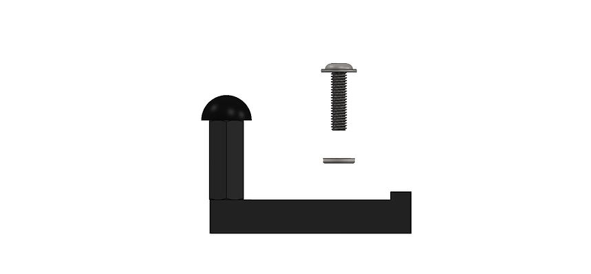
To secure the hard stop to the breadboard, an M6 fastener and washer is used (orient the washer face with the rounded edge away from the anodized surface, so no surface damage occurs due to washer edge burrs):

The placement of the hard stops vary depending on your plant configuration and needs, we recommend at least 10 millimeters of buffer, between the internal hard stop of the linear slides (EMB-LM1 or EMB-LM2) and the external hard stop. Remember, the internal hard stops of the linear slides should never be used as system hard stops, as they are not meant for external loading, only internal to hold the bearing balls in place. Please refer to the EMB-LM1 manual for additional details.
As an optional module to our EMB plants, the end-of-travel switches (EoTS) provide additional capability to EMB. The main use is for safety as a limit switch - when one of the switches is triggered, a fault occurs and the system stops. Another potential application of the EoTS is for homing the carriage motion.
The only contact point of the switch and the moving carriage should be the switch lever.
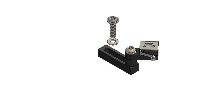
We offer a right and a left EoTS designed for each side of the linear slide.
To secure the hard stop to the breadboard, an M6 fastener and washer is used (orient the washer face with the rounded edge away from the anodized surface, so no surface damage occurs due to washer edge burrs):

These EoTS should not be used as hard stops, this will cause permanent damage. The switches should be placed right before a hard stop. Make sure the switch opens (clicks) but the switch doesn't bottom out before hitting the hard stop.
For placement, you can make use of the mount slot and the angle adjustment M6 fastener. Make sure all fasteners are secured before running experiments and no cables are on the travel path (cables not shown in renders).